 HutchBook.com
Charles G. Hutchinson Bottle Stopper
UNITED STATES PATENT OFFICE
CHARLES G. HUTCHINSON, OF
IMPROVEMENT IN BOTTLE-STOPPERS.
Specification forming part of Letters
Patent No. 219,729,
dated September 16, 1879; application
filed June 28, 1879.
To all whom it may concern:
Be it known that I, CHARLES G. HUTCHINSON, of
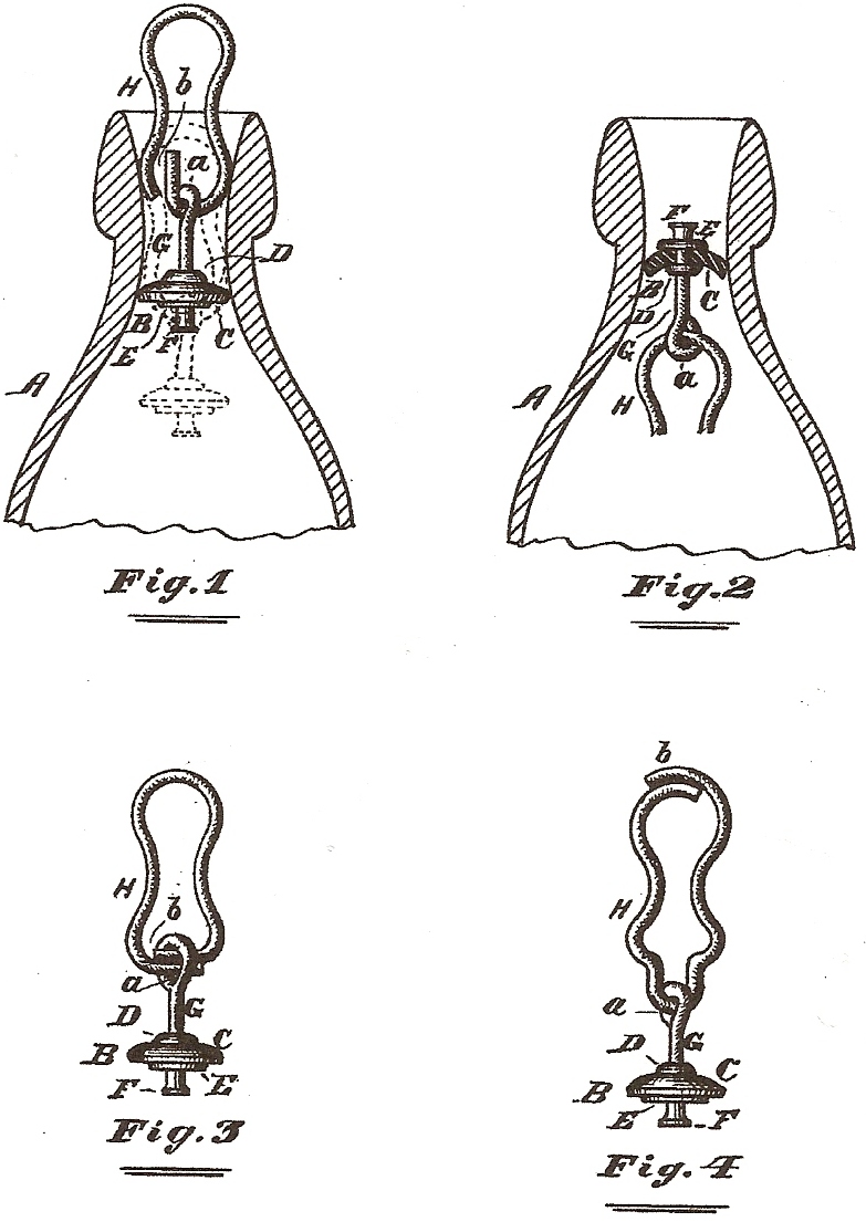
In the drawings, Figure 1 represents a vertical
central section of a bottle-neck provided with a stopper embodying my
invention, showing the stopper in the position it occupies when it
closes the neck. Fig. 2 is a
like representation, showing the position of the stopper when it is
arranged to be drawn from the neck of the bottle; and Figs. 3 and 4
represent modifications in the form of the yielding removable stem or
spring of the stopper.
Like letters of reference indicate like parts.
My invention relates to that class of bottle-stoppers
provided with a laterally-yielding spring extending upward from the
plug, and adapted to hold the latter in its open and closed position,
alternately, according to the adjustment vertically of the spring in the
neck of the bottle.
My present object is to render the spring and plug
capable of being removed from the bottle and of being easily detached
from each other after removal; and to that end this invention consists
in certain novel features of construction, substantially as hereinafter
set forth, relating to the plug and spring, and adapting them to be
combined in such a manner that the object referred to may be
accomplished.
In the drawings,
A represents the neck of a bottle.
B is a plug or stopper proper, which, with the exception hereinafter
specified, may be made in the manner usual in the construction of plugs
of this class. It may be
stated, briefly, that a common way of constructing these plugs is to
clamp a disk of rubber, C, or
other suitable material between two smaller metallic disks,
D and
E, the upper metallic disk
being smaller than the lower one, and the form of the metallic disk a
slightly concavo-convex form, the convex face being upward, as shown, so
that a tight joint shall exist between the plug and the neck of the
bottle when the plug is drawn up into the neck, and so that the plug
cannot be forced upward out of the neck, the lower metallic disk
preventing the rubber from being contracted sufficiently to admit of the
plug being withdrawn when arranged in the position shown in Fig. 1, but
not large enough to prevent that result when the parts are arranged in
the positions shown in Fig. 2.
It may also be stated that the concavo-convex form of
the plug, or a convex upper face, or rounded or bevel edges, all of
which features of construction serve the same purpose, may be given to
the rubber disk itself, independently of a corresponding form in the
metallic disks, and that even a flat disk of rubber will assume the same
form when drawn up into the neck of the bottle.
As all of these features of construction are common
expedients in making plugs of this class, I do not here intend to be
restricted to the precise construction herein shown.
F is a metallic
head or knob on the under or outer face of the disk
E, and
G is a metallic stem extending upward from the disk
D, and having an eye or
opening, a, in its upper end.
In practice the stem
G and head
F may be made of one
continuous piece of flexible wire, passing through the disks
C,
D, and
E, and headed on its lower end, and bent on its upper end, to form
the eye a, the disks
D and
E being held in place on the stem
G in any suitable way.
H is a
laterally-yielding spring, bent to fit the neck of the bottle, so as to
be adjustable therein vertically and to retain its position after being
adjusted either higher or lower, as may be desirable.
I make this spring in one continuous piece, the ends of which are
made to pass or lap each other, and both of which are left free or
loose, not being connected either to each other or to the plug
B, as represented at b,
and the overlapping parts of the spring may either be in contact with
each other, as indicated in Figs. 3 and 4, or they may be slightly
apart, as shown in Fig. 1; but in the latter case the upper part or end
of the open space thus made should be arranged to be sufficiently high
in the neck of the bottle to prevent the spring from being uncoupled
from the plug accidentally when both are in the neck of the bottle, as
will hereinafter more fully appear.
To couple the spring and plug together when a space
exists between the lapping ends, as shown in Fig. 1, I pass the upturned
end of the spring through the eye, when the plug will be freely
suspended by spring, as there represented.
To apply these coupled parts to the bottle, the plug and spring
are pushed down through or into the neck until the plug is free, as
indicated by the dotted lines in Fig. 1, the spring remaining in the
neck, and, by its lateral pressure, suspending the plug away therefrom
sufficiently to keep the bottle open.
In order to close the neck it is only necessary to
draw the spring upward until the plug fills the neck, when the spring
will also hold it in that position.
It will be observed by reference to Fig. 1 that the
upturned end of the spring is high enough to prevent the plug from being
accidentally uncoupled therefrom even when the stopper is in its open
position.
To remove this stopper wholly from the bottle, the
spring must first be pushed down into the body, when the head
F may be seized by a pair of
nippers, and the stopper entirely withdrawn, being drawn out in the
position the reverse of that necessary for its insertion, as indicated
in Fig. 2, the comparatively small disk being then underneath the rubber
disk, and allowing the latter to be contracted sufficiently to be
removed. After the stopper
has been removed it will be very easy, as will be perceived, to uncouple
and couple the spring and plug, so that a new or repaired part may be
substituted for one which may be worn or injured.
The operation of applying, withdrawing, and uncoupling
is the same as now described when the lapping ends of the spring are in
contact with each other, excepting that in disconnecting the spring from
the plug, the former should be expanded laterally until the plug can be
released.
It will be perceived that the spring
H, though capable of being
separated from the plug B, is a part of the stopper, which consists of both of these parts,
and that they cannot be uncoupled while the stopper is in the neck of
the bottle and in position for use.
When the ends of the spring are arranged in the
position shown in Fig. 4 it is not essential that they should overlap
each other, as in use they will be held from the eye
a; but may be carried thereto
when the parts are removed from the bottle by slipping the spring
longitudinally in or through the eye until the spring and plug can be
uncoupled by passing the eye between the ends.
As it is possible to remove the stopper by cutting the
disk C away sufficiently for that purpose, I do not here intend to be
restricted to a plug, B, when
provided with a head, F,
excepting as hereinafter specifically claimed, the spring and plug being
detachable from each other, in the manner described, whether the head
F be made or not.
Having thus described my invention, what I claim as
new, and desire to secure by Letters Patent, is –
The laterally-yielding spring
H, made in one continuous
piece, having free or loose ends, and adapted, substantially as
described, for automatic suspension at any point in the neck of a
bottle, in combination with a plug or stopper provided with an eye,
a, when the said spring is adapted, substantially as described, to
be moved longitudinally in the said eye, for the purposes set forth.
CHARLES G. HUTCHINSON.
Witnesses: F. F. Warner,
Chas. H. Tallmadge.
Comments:
Charles G. Hutchinson’s five bottle-stopper patents
are included in their entirety to serve as reference sources for
tracking their design evolution.
Also see:
U.S. Patent Number: 285,488 Patented: September 25, 1883