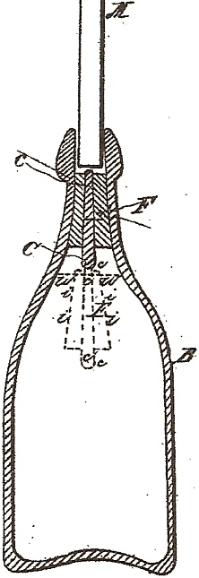
John Matthews, Jr. Bottle Stopper

John
Matthews, Jr.’s patent application specified:
I, John Matthews, Jr., of…
My invention relates to the constructing of an
internal floating stopper for a bottle, in such manner that when the
liquid is poured into the bottle to the required height – say to the
dotted lines W W in the
drawing – that the stopper shall present itself in proper position for
being seized by an instrument and drawn to its seat in the mouth of the
bottle.
It is obvious that if the stopper were an elastic
spherical valve no difficulty could be experienced in seizing it in any
position and drawing it to its seat in the neck of the bottle; but in
practice it has been found difficult to prevent such ball-stopper from
losing its true spherical form after remaining for a long time in the
neck of the bottle, especially when subjected to a high internal
pressure, as would be the case if aerated liquids were inclosed (sic) in
the bottle. In consequence
of the rings and other indentations thus permanently impressed upon such
ball-stopper, it has been found difficult to close such bottle perfectly
a second time, unless the same part of the ball could again be brought
exactly to its former place.
This I accomplish by weighting the stopper, or so disposing the
materials used in its construction that one part of the stopper shall
always be presented toward the mouth of the bottle in a convenient
position for being seized by instruments and drawn to its place.
In practice it has also been desirable to secure some
ready means of seizing the stopper and drawing it to its seat in the
mouth of the bottle.
My invention consists, principally, in accomplishing
this by constructing my stopper with a central rod of iron or other
metal which is susceptible of being rendered magnetic, or which may be
attracted by a magnet, and thus drawn to its seat in the neck of the
bottle.
In the drawing…B
represents the bottle filled with liquid to the dotted lines
W W.
The red dotted lines I
I I I, c, and F show the position of the stopper while floating on the liquid.
C represents the central rod of iron, which projects below the
cork-float F and causes it to
float in an upright position.
M represents the magnetic plunger, which, being
lowered into the bottle, attracts the central bar, C, with sufficient
force to enable the stopper to be drawn to its place in the mouth of the
bottle…
I am aware that an internal floating bottle-stopper
has long been known, and that therefore that method is not new.
Comments:
This patent was included here to provide insight into John Matthews, Jr.’s thought process prior to designing his Patent No. 67,781 of August 13, 1867. Matthews indicated this stopper was made of cork with a central metal rod, but his specifications don’t explain how it would be placed in the bottle prior to filling. It doesn’t seem practical to install a cork stopper during the process of blowing and finishing the bottle. Most likely this invention proved to be impractical, helping to explain why no known completed examples of this closure have been found.
 HutchBook.com