 HutchBook.com
James Terry Bottle Stoppers (2)
James Terry’s patent
application was filed December 15, 1884 and specified:
I, James Terry...of
Hartford…Connecticut, have invented certain new and useful Improvements
in Removable Bottle-Stoppers, of which…My invention relates to
improvements in bottle-stoppers of the class which act upon the inside
of the bottle and have a contractile valve-washer for the purpose of
removing the stopper from the bottle when desired.
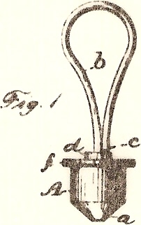
In the accompanying drawings, Figure 1 is a side
elevation of my bottle-stopper.
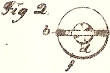
Fig. 2 is a plan view of the same.
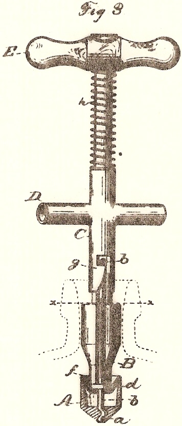
Fig. 3 is a sectional view of the same, partly in elevation,
together with a side view of the instrument for contracting the
valve-washer…
A designates the
head of my bottle-stopper, the same having a cup-shaped recess in its
upper side and a cone-shaped hub,
a, at its lower end, as shown in Fig. 3.
This cup-shaped head is attached to a wire loop,
b, which loop and head are united by casting the head upon one end
of the wire, while the short free end of the wire loop extends downward
by the side of its body to a point near the head, and serves as a stop,
c, Fig. 1, to limit the upward
movement of the solid disk d,
which rests upon the upper side of the valve-washer
f…this stopper may be inserted
within the mouth of the bottle for use therein in the ordinary manner of
bottle-stoppers which act upon the inside of the bottle.
In order to contract the valve-washer
f into a smaller diameter for
removing the stopper, I provide the instrument shown in Fig. 3.
This consists, essentially, of a slotted shaft, B, of a form
which will extend down through the neck of the bottle…The slot in the
shaft B is wide enough and long enough to receive the wire loop b, as
shown. Upon the body of the
shaft B is a sliding tube, C, provided with a pair of hooks, g, for
catching upon the bow of the loop b, as shown in Fig. 3.
This tube C is also capable of rotating slightly upon the shaft B
for the purpose of bringing its hooks g into engagement with the loop b.
This tube is also provided with a handle, D, for sliding it
longitudinally upon the shaft B.
I have also represented the upper end of the shaft B as provided
with a handle, E, for convenience of operating the instrument…
Comments:
This is the second of three closely-related patents
filed by James Terry.
Terry’s specifications went on in mind-numbing detail to explain exactly
how the instrument he designed for removing stoppers worked.
It’s no wonder bottlers (and customers) welcomed the advent of
Painter’s Crown Closure. It
is unknown whether or not Terry achieved any success at marketing his
stoppers and stopper removal instrument.